A disruptive approach to mmWave for wireless telecom applications
![]()
This article will discuss a disruptive antenna technology that is based on dielectric waveguides that travel along a medium, traditionally known as a polyrod. In contrast to widely used electronically steerable phased arrays, polyrods do not require per-element phase shifters, leading to a drastic reduction in cost, design complexity and power consumption. In fact, the polyrod, dielectric waveguide antenna (DWA) element allows for beam pointing rather than beam forming. This paper provides some historical context, introduces the technology and finally discusses different use cases and applications.
The Polyrod
Traditionally, the advantages of a polyrod were light weight, low cost, reduced volume, ultra-wide bandwidth and stable radiation patterns. The ideal use cases were satellite communications, radar systems, chip-to-chip communications and mmWave imaging. ED2 re-invented the approach and realized its true potential for 5G and beyond.
In engineering and product design, the solution is always a consideration of many comparisons and trade-offs. For a system, DWA-based or phased arrays are no different. This article does not suggest that DWAs will replace phased arrays. The intention is to highlight that DWAs enable low cost, low power and provide ultra-wide bandwidth. DWAs can be an alternative to phased arrays for appropriate applications.
Bell Labs Polyrod Technology
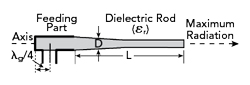
Figure 1 Dielectric rod antenna description.
The “polyrod antenna” was developed by Bell Labs from 1941 to 1944. A rod or wire of dielectric material is a well-known transmission line and shown in Figure 1. A portion of the energy travels on the outside of the rod. Irregularities in the surface of the rod cause a radiation of the signal. This “leaky” transmission line can be used as an antenna structure. ED2’s polyrod antenna has achieved approximately 20 dBi gain and supports either dual linear or circular polarizations.
Bell Labs described it this way: The tendency toward radiation inherent in the dielectric guide is turned to advantage, however, in a new form of radio antenna. Here the objective is to encourage radiation from all parts of the dielectric rod. In progressing along the rod, therefore, power is gradually transferred from within the dielectric to the space outside. At a point where the transfer has been effectively completed, the rod can be terminated abruptly. By proper design, this radiating structure is an end fire antenna. Since it has been most often fabricated from polystyrene, it has become known as the polyrod antenna. It is especially useful for microwaves.1
New Challenger for mmWave Phased Arrays: DWA
In contrast to electronically steerable antenna arrays that are commonly used in 5G base stations and UEs, ED2’s patented DWA elements enable new equipment that will beam point. In its basic form, the DWA is a cylindrically or cone-shaped dielectric rod that acts as a waveguide, radiating a beam whose width and gain is proportional to the RF frequency and rod length.
As stated before, DWAs offer a few advantages over electronically steerable arrays, including lower cost, lower power consumption and more consistent beam characteristics. In terms of beam characteristics, DWAs produce symmetric antenna patterns, back lobe suppression and zero scan loss.
ED2 has patented linearly and circularly-polarized antenna elements, commercializing these products through partnerships. The DWA can easily be modified to support any mmWave frequency used by telecom. At 28 GHz center frequency, DWA designs that achieve 20- to 90-degree beamwidth (depending on polyrod length), with 20 dBi gain along the antenna boresight. These antennas also benefit from being dual polarized. DWA can achieve uniform signal coverage over a targeted area making it a great fit for mobility applications.
In 2018, it became clear that a DWA alternative to phased arrays would provide benefits to the 5G ecosystem. This alternative antenna should achieve a few specific requirements or goals. The new DWA requires a feed that will induce two linearly polarized signals into the rod that are orthogonal to each other. This new DWA will act as an end fire antenna when excited by a conductive resonator and generate a highly directive narrow beam with no phase shifters needed.
First Design Attempt
ED2 took a fresh approach to phased array design and concluded that the trade between circular and linear polarization was a toss-up. For the first concept, the team decided to design a circularly-polarized antenna element.
The circularly polarized antenna element would transition to a waveguide in organic substrates. The team leveraged experience with passive surface-mount waveguide components to make the waveguide launch successful. Next, they needed to integrate the waveguide launch with a rod using an organic material. This led to an intensive CNC and lathing process that proved to be expensive and labor intensive. By the end of this first version’s development, they had not only created 3D spiral exciters with a rod that can change in gain by adjusting its length, but also achieved the predicted performance. The exercise led to what is used today and taught significant lessons to the team.
DWA Design
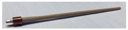
Figure 2 Cylindrically shaped polyrod.
Although the polyrod concept has been around for some time, its use in 5G communications had not been explored before. The gain and beam characteristics of a polyrod antenna depend on its geometry and the operating frequency. Specifically, for a cylindrically shaped polyrod of electrical length Lλ (where λ is the wavelength), the half-power beamwidth (HPBW) is  . As an example, producing a 20-degree HPBW requires a polyrod of length Lλ = 9λ; this is slightly more than 9 cm at 28 GHz frequency (see Figure 2). Antenna length and geometric properties can be adjusted to achieve any desired beamwidth at any target mmWave frequency.
Expensive and Labor Intensive
The team learned that the initial design was not cost-effective to manufacture for a number of reasons. The material in the stack-up had an overall thickness of approximately 280 mil, and most board shops cannot handle stack-ups that large. Manufacturing required a shop that could handle an overly thick board and build per our manufacturing drawings. Only a single supplier was available, at a high cost. The cost of the PCB rod represented a majority of the overall cost of the antenna, regardless of manufacturing quantities. The new design incorporates a significantly thinner stack-up, expanding the number of outsourced PCB shops that could support a lower cost antenna (see Figure 3).
Besides high costs, the original design presented manufacturing challenges. The material was brittle, thin and long, making post-processing difficult; and, it was prone to failure from vibration. Concentricity was difficult to repeat. A 10 percent failure rate during machining was experienced. Tight design tolerances and machining difficulties made it unfeasible to build in a timely manner and suggested that fixtures and new machines were needed. With the high labor requirements, machining this part became 20 percent of the overall cost. And once built, the polyrod cap and connector required further assembly, adding additional fabrication time and cost.
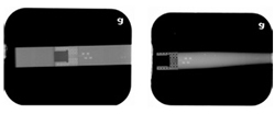
Figure 3 Dielectric rod antenna x-ray images before lathing and after lathing process.
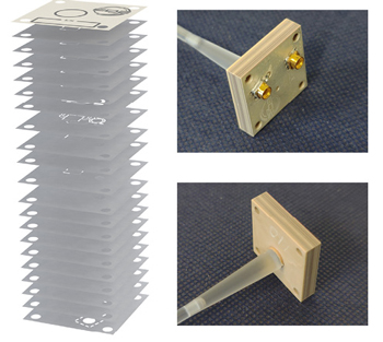
Figure 4 DWA stack-up.
Read more at Microwave Journal.